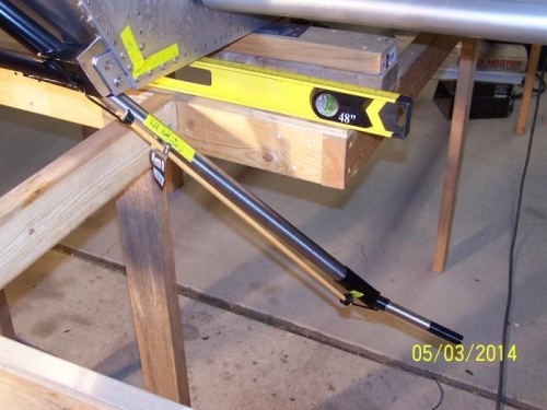
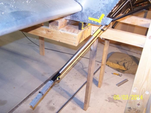
Install jig for setting main landing gear toe in. - Spacer 7/8" diameter x .058" wall x 3/4" long tube on inboard end of L01-08 L&R Axle Assembly - Install L03-08 L&R Axle Assembly to L01-03 x 2 Gear Leg. - 1" x 1" x 10" angle, clamped to vertical tube of L01-08 L&R Axle Assembly - 1" x 1" x 10" angle, clamped to axle of L01-08 L&R Axle Assembly - 1/2" x 3/4" x 4" bar stock spacer x 2 in front of angle on axle so straight edge will clear gear legs - 1" x 1" x 6' Angle for straight edge clamped across L01-08 L&R Axle Assembly
Using 6' straight edge to ensure proper toe in, clamp L01-08 L&R Axle Assembly to L01-03 x 2 Gear Leg.
Remove jig and L01-08 L&R Axle Assembly & L01-03 x 2 Gear Leg. In drill press step drill L01-08 L&R Axle Assembly & L01-03 x 2 Gear Leg to 1/4".
Re-install L01-08 L&R Axle Assembly & L01-03 x 2 Gear Leg to P38-01 Engine Mount. Install jig and verify proper toe in.
Assemble: - 3.40 / 3.00-5 tube x 2 - 11 x 4.00-5 8 Ply Rating Cheng Shin Tire x 2 - Azusa 5" Tir-Star Wheel x 2 Note: Wheel casting says "Max inflation pressure = 30 psi", DWG SNX-L07 says "Inflate to 50 psi". Go figure. - P/N 1137 x 4 Tapered Wheel Bearings - ACV-B01-24 x 2 Brake Plate - ACV-B01-20 Main Body - ACV-B01-21 x 4 Brake Puck - ACV-B01-25 x 4 Brake Piston - ACV-B01-26 x 4 Piston o-ring (with o-rings to outside of main body) - L07-10 x 2 Wheel Pant Mount Plate (after deburring)
Left Gear Leg & Axle with Spacer Installed #3124
Right Gear Leg, Axle, Spacer & Angle Installed #3126