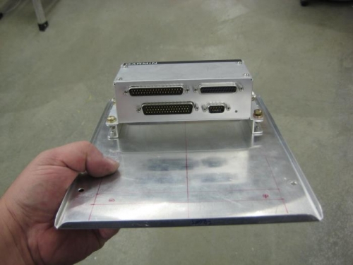
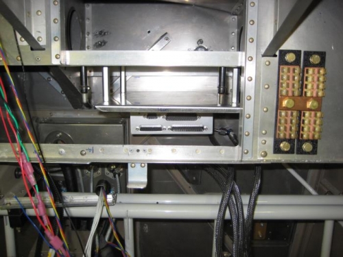
I decided to mount the GEA24 on the bottom of the previously fabricated rack. This took some planning, as the GTR 20 second remote com will be mounted in the middle rack. The upper rack will support the ECUs.
I marked the GTR20 outline and mounting holes on the middle rack. I then located the gEA 24 on the opposite side. The issue was that the mounting bolts for the GEA 24 would interfere with the mounting surface used for the GTR20. The solution was to fabricate risers from 063 x 1/2" C channel. Doing so removed the interference and actually made the wire routing from the GEA 24 better. As a side benefit, it is easier to access the DSUB connectors on the GEA 24.
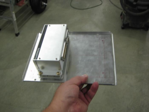
Standard techniques were used to fabricate the risers, install required nut plates, and rivet them to the rack using CS4-4 Flush Blind rivets.
The rack was then temporarily installed with clecos and the GEA 24 attached to the risers.
Next, I separated the EGT and CHT harness wires in to even and odd banks. Using heat shrink tubing in sevral places, two pigtails were made. The wires were then fed throught the firewall pass through. As recommended by Steinair and Garmin, all other wires were removed from this pass through and it will be exclusively for the EGT and CHT wires, thus keeping clearance on all other potential EM wiring.
Some thought was given to FWF routing of the wires, and I think the most optimum routing is below the fuel rail and outside of the intake/exhaust tubes. I may insulate the wires with short lengths of fire sleeve where the are in proximity to the exhaust pipes.
The plan is to mount the GAD 29 on the top rack aft of the ECUs but I will wait on final determination until I receive the new System32 ECUs.