
|

|
|
|
Pete's RV-8 Web Site
|
Date: 6-1-2013
|
Number of Hours: 5.00
|
Manual Reference:
|
Brief Description: Circuit testing
|
|
Wiring the intercom was one of the more challengiing tasks to date. I installed jacks in the front and rear cockpits for phones, mics, and auxiliary audio input (music). Each jack is wired with a three conductor cable with shield. Two of the conductors go to specific sockets on the intercom while the third wire is spliced to the shield and grounded at the panel. There are also a couple cables that come from the radio which are two conductor with shield. In addition, I used a 3PDT switch on the aux audio inputs to selectively choose which cockpit to route to the intercom sockets.
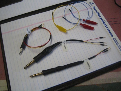
I was careful and double checked the schematics as the wires were connected but still went away wondering if every circuit was properly connected. So, I decided to find a way to check each wire from the jacks to the DB25 connector at the intercom. My solution was to make three test aids from an old set of headset plugs and a 1/8" stereo headphone plug found at RadioShack. You can see the aids below in picture one. I have a wire lead from the ring, tip, and barrel of each plug with a gold pin (Dsub male pin) attached. The three leads are marked tip, barrel, or ring. I also made some short leads with alligator clips on one end and either a pin or socket (again, Dsub pins or sockets).
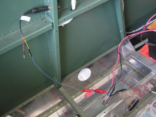
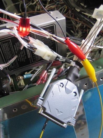
To test, I plug into the jack, select the contact to test (ring, barrel, or tip), and apply a 12V power source (+V to lead and neg to ground). I then go to the Dsub connector and plug into the appropriate socket per the intercom schematic and attach to a LED lamp (other lead grounded). If it lights, I have the correct socket. I went thru this procedure for all the jacks and found one problem on the aux audio which turned out to be a faulty contact in a Molex connector at the 3PDT switch.
I also found an issue with the audio connections between my Garmin 250XL GPS/Comm and the intercom sockets. I am working to resolve this problem but it looks as if two wires have been reversed at the radio connector (the pin and wire color specs are not matching the
|
|
Testing Aids
|
|
Power to Jack Contact
|
|
Correct Socket?
|
|
|
|
|
|
|
|
|
Copyright © 2001-2024 Matronics. All Rights Reserved.
|