Brief Description: Installation of ground adjustable rudder pedals
Very soon it will be time to invert the fuselage to match drill the landing gear and install the forward bottom skins on the fuselage. I decided the cleanest way to install the rudder pedal assembly would be to match drill and rivet the mounting rails now before adding the forward bottom skins. In order to locate the rails on the cockpit floor it was necessary to first assemble the attach angles, thrust washers, rudder pedals, brake cylinder arm, and the rudder axles. As a first step in this assembly two thrust washers had to be fabricated from pieces of UHMW plastic.
The kit includes a couple pieces of UHMW material which are barely large enough for the task and getting them just right takes a little time. The material isn't the easiest to cut although it drills reasonably well with both standard and Unibits. I made a pattern for the parts from heavy card stock and traced it onto the plastic. I then drilled the large 7/8" hole, slipped the material over the rudder axle and traced the final shape directly onto the plastic using the actual backet on the rudder axle. I also match drilled the 3/16" holes before removing the UHMW and cutting it to final shape.
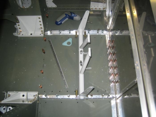
I then assembled the parts shown in image 1 below, positioned the rails/angles per the shop instructions and match drilled to #30. I will deburr, prime, and rivet the rudder angles to the fuselage floor during my next shop session. I also need to final drill the brake cylinder bracket to the rudder axle and insert the bolts.