1. Drilled 1/8" & clecoed the main spar to the rear ribs.
2. Drilled #20 & clecoed the mail spar to the rear ribs.
3. Sighting down across the aft portion of the rear ribs revealed that 3 ribs appeared to be out of line on the low side.
4. I laid a straight edge across the aft part of the rear ribs, unclecoed the low ribs one at a a time, raised them to the straight edge (or close to it), clamped, and then drilled the 1/8" holes to #20.
5. Drilled the remainder of the ribs/rear spar to #20.
6. Marked the 45° cut on the outboard end of the rear spar.
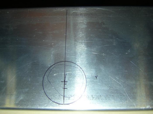
7. Measured & marked the location of the aileron control rod hole on the rear spar. See Fig. 1.
8. Removed the clecoes from the rear spar and removed the spar from the ribs.
9. Dwg. 6W7 shows the center of the aileron control rod hole 20-mm above the bottom flange. But the bottom flange is bent closed ~12°, and it is not clear from where the 20-mm flange-hole center should be measured. This position app
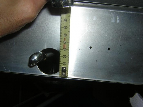
10. Inspected the aileron control hole in Lauren Ackerman's 601XL QBK wing (Fig. 2). The hole is almost on the bottom flange, ~1-mm separation at the edge. That looks to be just where the plans would put it, depending on from where you measure on the flange. Looking at the control rod position and the aileron control horn, it appears to me that the hole could be about 3 or 4-mm higher without scraping on the control rod clevis. That assumes that the metal hinge does not flex downward significantly.
11. Fig. 3 shows the best photo I can find in the PAM of the aileron control rod hole.