1. Drilled#30 and clecoed all the rivet holes for the aileron and channel and hinge.
2. Disassembled the channel and servo from the aileron.
3. Prepared a DB-9 connector as described in my 12/7/07 and 12/11/07 logs.
4. Soldered the servo leads to the female DB-9 connector in the same pattern as used for the rudder:
Pin Wire 1 Blue stripe wire--to indicator 2 Green stripe wire--to indicator 3 Red stripe wire--to indicator 4 White wire-- +12V to this wire drives servo in 5 White wire-- +12V to this wire drives servo out
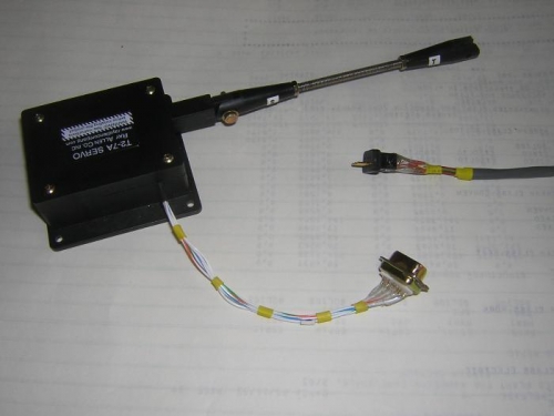
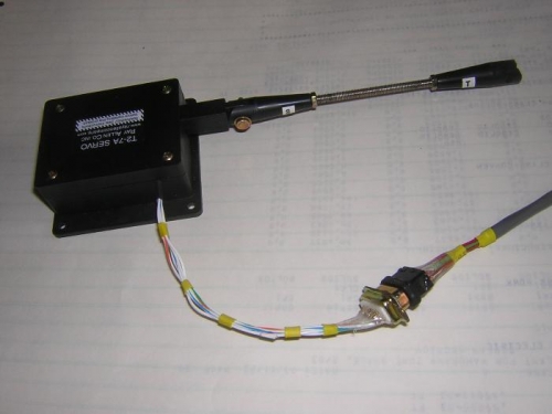
5. Crimpted the cable leads to the male connector pins in the same pattern as used for the rudder:
Pin Wire 1 Brown 2 Green 3 Red 4 Black 5 White
I had to pull the pins through the connector to get the pins to properly engage the connector. I do not recall doing this on the rudder connector, so if that connector is ever disassembled, I must be careful to make sure the pins are properly engaged. See Figs. 1 & 2.
6. Mated the male and female connectors and checked the servo for correct operation. It worked fine. I did not test the indicator or the switch.