All the work on pages 1-5 of the PAM was completed in manufacture (C.I.M.) of the kit.
1. Cut a piece of 2x4 with chop saw to 13-mm length, probably ±0.25-mm.
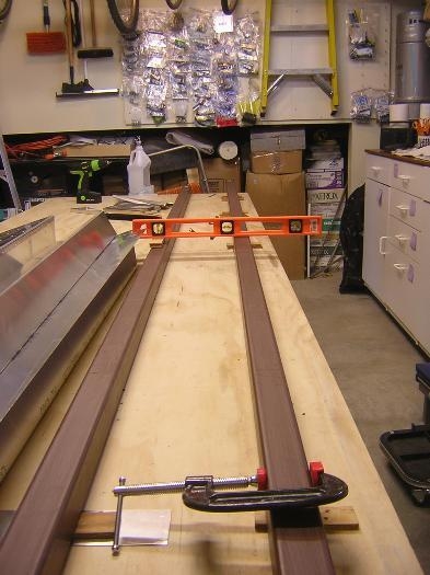
2. Placed a 1/4" plywood shim under each rail, 1-ft from the N end, to set a common pivot point for the two rails. Added a piece of 0.040 aluminum to the shim under the E-rail so that the tops of the two rails were were perfectly level at the pivot point. Put a C-clamp on the w-most rail as a stop to assure that I was placing the aileron at the location of the pivot point. Using the 13-mm 2x4 as a reference, I shimmed the S-end of one rail so that the rail was 13-mm higher than the other rail at a point just equal to the length of the bottom of the aileron. See Fig. 1
3. Drew rivet lines with 9-mm edge distance. Nine mm appeared closer to the center of the flanges than 10-mm.
4. Place the aileron skin right side up on the rails so that the O.B. trailing edge was 13-mm above the forward edge.
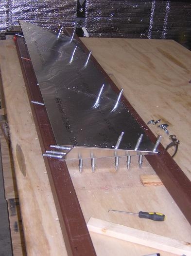
5. Placed the 3 straight ribs into the skin and aligned them so that the rivet lines showed through the pilot holes in the skin. Drilled #40 and clecoed the front side of the aileron skin to the ribs.
6. Turned the aileron over so that it was upside down, with the leading edge now on the raised rail and the trailing edge on the level rail. Since the aileron was upside down, this is equivalent to raising the trailing edge by 13-mm.
7. Aligned each rib so that the rivet lines showed through the pilot holes, and drilled #40 and clecoed each rib. I drilled from the trailing edge to the forward edge.