Brief Description: Install servo and check operation
1. Marked the required position and orientation for the control-rod notch in the elevator cutout channel.
2. Removed the elevator cutout channel from the elevator and deburred.
3. Cut the control-rod notch into the channel. Started with tin snips. Cut very close to the line on the straight part, but left about 3-mm of metal around the curved radius. Then used a rotary carbide cutting tool in the drill press to remove metal up to the curved line. Finished off with a hand file and deburred.
4. Drilled, deburred, scoured, primed, and then riveted the trim tab control horn to the trim tab.
5. Positioned, drilled, and clecoed the servo to the top elevator skin.
6. Cut the control rod so that the control rod assembly would have a minimum length of ~105-mm.
7. Clecoed the trim tab to the hinge and the hinge to the elevator.
8. Connected the control rod to the servo and to the control horn.
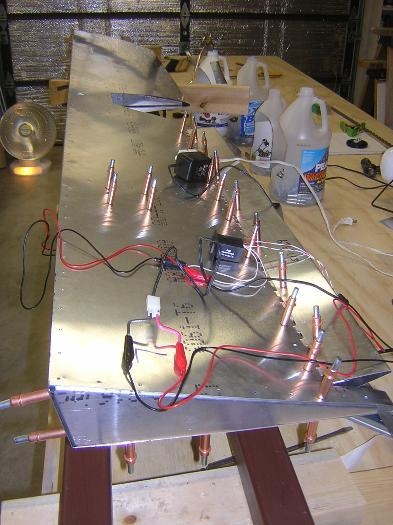
9. Used an old DC power supply to provide a 12-volt current to test the trim tab system. I connected the power supply to the control switch and the control switch to the servo using test leads with alligator clips. See Fig. 1. This power supply will provide a very convenient power source to test electrical systems as we progress.
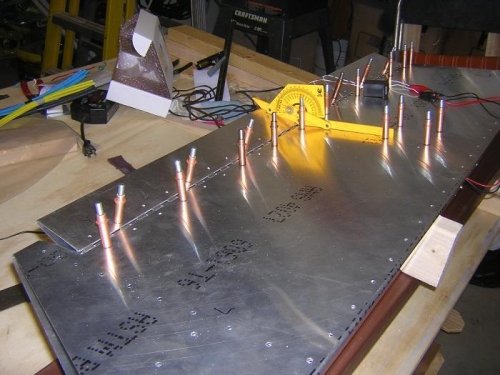
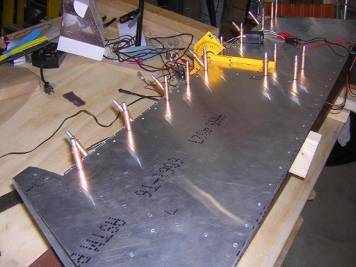
10. Exercised the servo to verify free movement of the trim tab. Then I measured the angle of deflection of the trim tab, and adjusted the length of the control rod to meet the specs of 20° up and 40° down. See Figs. 2 & 3. After adjustment, the control rod was about 118-mm long vs. the value of 115-mm given on Dwg. 6-T-6.