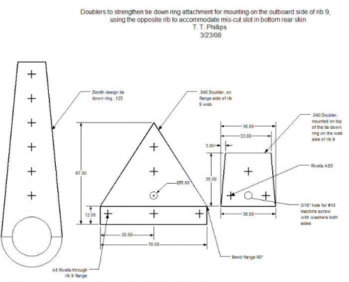
Brief Description: Design doublers for tie down ring
1. I am concerned that mounting the tie down ring on the outboard side of rib 9 where the rib 9's are reversed (left rib on right wing, and vice versa) would signifcantly weaken the tie down for sideways wind loads. So, I designed doublers to reduce the possibility that the tie down would rip out of rib 9 in the reversed configuration.
2. The 1st component is a triangular shaped doubler on the flange side of rib 9 that would spread the sideways load from the tie down ring over at least 3 skin-rib flange rivets and over a more substantial portion of rib 9. See the middle drawing in Fig. 1
3. The 2nd component is a doubler that goes on top of the tie down ring, just above the skin.
4. The 3rd component is a #10 machine screw (or 1/4" bolt) with washers replaces the bottom rivet. This is designed to spread the bottom load over a larger area of the doubler.
5. the 4th component is to replace the 2nd from the bottom A5 rivet with an AS5 rivet. A5 Aluminum/steel mandrel rivets have typical tensile strengths of 490 lbs vs. 1130 for stainless/stainless AS5 rivets.
6. the 5th and final component are two AS5 rivets near the corners of the doublers that will force the ring-side doubler to act as a fulcrum so that side loads on the ring are not concentrated on the bottom rivet.