Brief Description: Cut & Adjust aileron trim tab control rod
1. Drilled out the control horn rivets. Scoured and primed the joint line. Riveted the horn back in place.
2. Clecoed the trim tab and hinge in place.
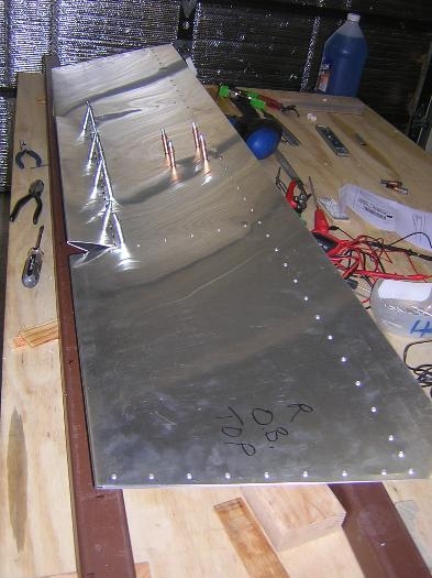
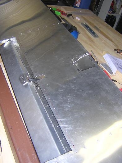
3. Determined that for my placement of the servo, the pin-pin control rod length should be about 108-mm rather than the 120-mm shown on 6-ATO-1. Cut the threaded rod so that I could vary the control rod length ±10-mm and still have the rod threaded at least 10-mm into to each clevis. See Figs. 1 & 2.
4. Installed the control rod to the servo and trim tab. Using the same DC power supply noted in my 12/4/07 log entry, I checked out the trim tab operation. Adjusted the control rod length for even up and down operation. I had to file the base of the slot in the trim tab clevis so that the clevis would not bind on the control horn.
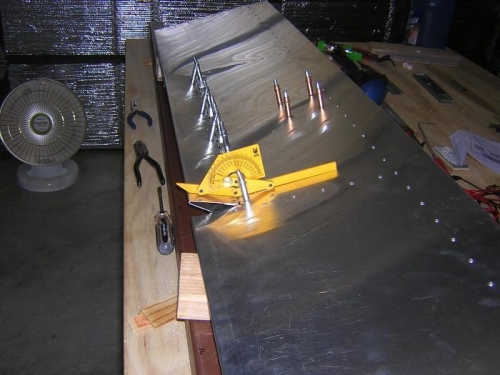
- DWG 6-ATO-1 specifies that the trim tab should deflect up and down by 25°. In my system the best I could obtain with the the supplied control horn was 20° up with 19° down.
- I conclude that probably +20° -19° movement of the trim tab is adequate. See Fig. 3.
- The pin-pin length of the control rod for this amount of tab deflection was 120.5-mm. That was a surprise, because 6-ATO-1 shows the distance between the rear edge of the servo and the tab hinge as 145-mm. The actual distance in my aileron was 133-mm, so I expected the length of the control rod to be the 12-mm less than the 120-mm length called out in 6-ATO-1. None-the-less, the tab appears to function perfectly.