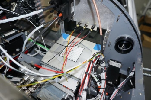
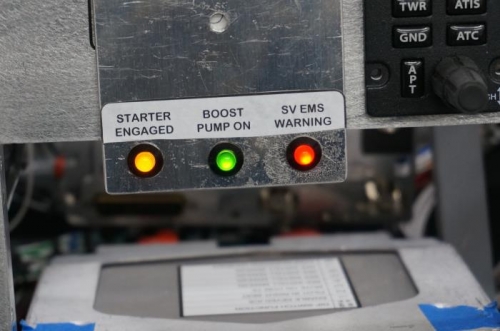
Soldered wire leads onto three LED lights (one red, one amber and one green). These three LEDs will be used as the three panel mounted indicator lights. The red one will be for the Skyview EMS external warning light, the amber one will be for the starter engaged light and the green will be for the boost pump on light.
Cut wires to length for the indicator light power and ground. Labeled the wires. Routed the wires to the starter contactor, boost pump VP-X pro and avionics bay ground block. Secured the wires to the existing wire bundle with string ties. The wires will connect to the indicator lights with a molex connector to allow removal of the panel.
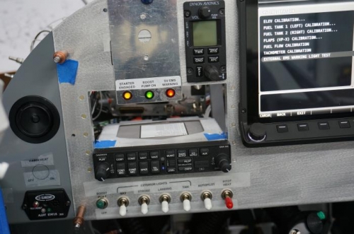
Drilled 3/8 inch holes in a scrap piece of aluminum. Installed the indicator lights and glued a label to it. Temporarily clamped the aluminum plate to the panel with the indicator lights in the opening for the IFD440. This location is a couple of inches lower than where they'll be located eventually, but I didn't want to drill the holes in the panel until I'm sure of the configuration.
Temporary hooked up all wiring and functionally tested the lights. The EMS warning light came on when I ran the external EMS warning light test on the Skyview screen. The boost pump light came on when the boost pump switch was turned on and the starter light came on when I connected it's power lead to the battery.