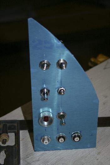
We decided to use the trianglular area to the right of the instrument panel for the Master, Alternator, and engine electrical group (Starter, mags, boost pump). This group is only used at startup and shut-down.
Because the panel is fairly far along in the assembly process, I didn't want to screw up. I decided to make a prototype from some scrap aluminum first. Good thing. I ended up re-designing it about 4 times over the course of the day.
Finally, I drilled the holes for the various switches and breakers. It came out looking great.
We are going with P-Mags. We decided to use a three position switch for each mag. The lower posistion will ground the p-leads (engine off); the middle position will be used for test (self powered mode) and the upper position will be used for start and normal flight. The runup check will move the switch to the middle position - there should be no change if the PMag generator is working, then to the lower position to ground out the mag (resulting in an RPM drop), return to center to see the RPM return in self powered mode, and then to up for battery and self-powered redundancy.
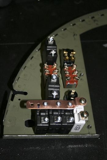
I also fabricated a buss-bar for the engine sub-panel. This simplifies the wiring substantially.
We were short two circuit breakers - now on order.