
|

|
|
|
CHUCK'S WEB SITE
|
Date: 3-28-2024
|
Number of Hours: 2.90
|
Manual Reference:
|
Brief Description: CAD Modelled The Two-Piece Slip-Joint Pipe
|
|
Now that the right 3-to-1 reducer body has been 3D scanned, CAD modelled, 3D printed, and verified to fit on the exhaust headers, I started CAD modelling the single exhaust pipe that will exit from the 3-to-1 reducer body.
I initially modelled a single fixed exhaust pipe section that was at almot right angles getting to the tunnels. The angles needed to be decreased for smoother flow, and two points of rotational adjustability need to be added to allow the pipe to be positioned first to hit the tunnel opening, and then to be angled down to go out and below the cowling bottom.
The goal is to reproduce the reducer bodies as exactly as possible for both the left and right sides, then produce a 2-piece exit exhaust pipe that has rotational positioning adjustability in two places so the exact custom run to the exhaust tunnels can be shaped on the 3D printed model, locked in the correct position, then taken in to a customer exhaust shop to be reproduced, and welded onto the existing steel 3-to-1 reducer bodies that came with the Jabiru 3300, after the original single exhaust pipe run has been cut off.
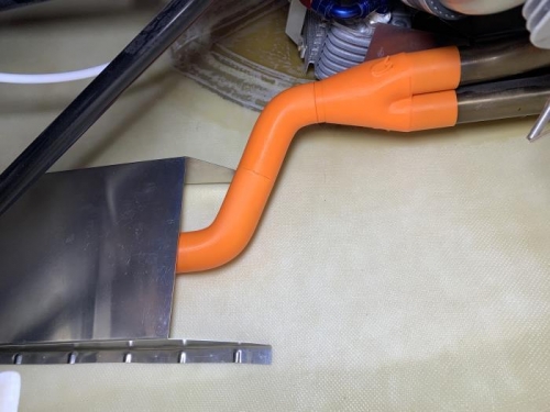
Once the pipe was modelled, it was 3D printed and fit was checked with expected tunnel opening location.
|
|
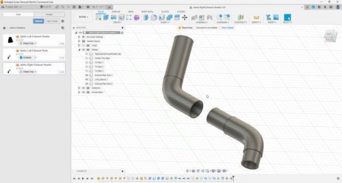
The adjustable two-piece slip-jointed exhust pipe sections 3D modelled.
|
|
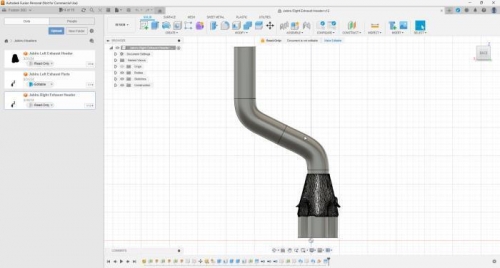
The final CAD model for a complete adjustable exhahust model.
|
|
Final adjustable 3D model of complete exhaust pipe assembly.
|
|
|
|
|
|
|
|
|
Copyright © 2001-2024 Matronics. All Rights Reserved.
|