
|

|
|
|
CHUCK'S WEB SITE
|
Date: 4-9-2022
|
Number of Hours: 9.90
|
Manual Reference: SNB-L01
|
Brief Description: Main Gear Legs Final Mounting.
|
|
I heard back from Kerry at Sonex Tech Support. He indicated the leg, as provided, would go into the inner tube/sleeve in the weldment, it just may have some welding slag, or may just be an extremely tight fit, but it had to go in the sleeve, even if it has to be chamfered and greased at the end and pounded into the sleeve. The 3 1/2" distance from the top of the weldment tube is also where the 1/4" hole must be for bolting the leg in the weldment.
With this info, I chamfered the drilled end of the legs, lubed them with white lithium grease, then pounded them with a hammer intil they went into the upper tube/sleeve and the hole in the leg lined up with the hole in the weldment at 3 1/2" from the top. I had to use an alignment line drawn on the leg lining up with the leg's hole in order to see (through the weldment hole) how lined up the hole in the leg was with the hole in the weldment as it was pounded in, as the leg could not be twisted at by hand. I typically subscribe to the concept that if this much force is required to make something fit, it should not be forced. However, per Sonex's instructions, the legs did go into the weldment to the proper depth, and were bolted at the specified distance from the top of the weldment tube.
With the tops of the main gear legs properly mounted first, there was too much leg length to seat the axles on the other end of the leg(s) and have the specified 14 3/8" distance below the bottom skin plane (with no load on the gear).
Measured the amount of leg to be trimmed off so the center of the axle tips, when set with 0.7 degrees of toe-in, would be at the specified 14 3/8" below the extended plane of the bottom skin. Used a hacksaw and tapping fluid to trim ~ 5/8" off each leg.
Installed both axles on their legs until they bottomed-out on the leg end, attached a piece of aluminum square tube stock across from one axle to the other to set the 0.7 degree toe-in, then marked and drilled the 1/4" mounting holes in the axle sleeves and legs. Bolted both axles on.
|
|
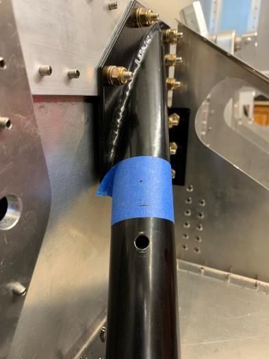
The upper mark on the blue tape is where the new 1/4" hole was placed to be 3 1/2" down the tube.
|
|
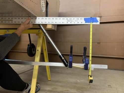
Extending the bottom skin plane out to measure down to the center of the axle with toe-in set.
|
|
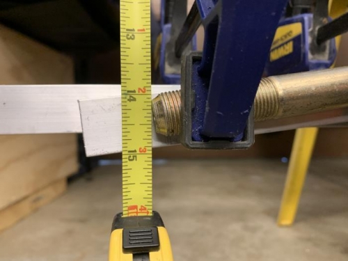
Left axle tip at exactly 14 3/8" below bottom skin plane (right axle < 1/16" off). Toe-in 0.7 deg.
|
|
|
|
|
|
|
|
|
Copyright © 2001-2024 Matronics. All Rights Reserved.
|