Brief Description: Rudder - Match Drill and Debur Components
Trim the excess material from R-710 rudder brace. Fit the R-710 between R-405PD and R-904. Cleco the aft edge of R-710 to the bottom of R-904 and drill #30. Match drill through the forward edge of R-710 using the holes in R-405PD as a drill guide.
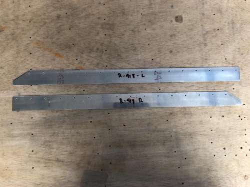
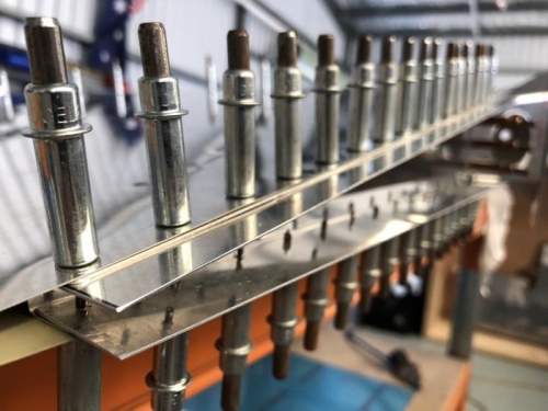
Make the R-918 rudder bottom attachment strips shown on DWG 7 and clamp them in place. Drill them to the skeleton, using the existing holes as drill guides.
Disassemble the rudder and deburr all the holes. Dimple the skin, spar and ribs.
The aft three 3/32 holes in the upper edge of R-901-L and R-901-R should be drilled to #30 and dimpled. These holes will later be used to attach the R-909 rudder tip. While the holes could be opened up to #30 when drilling the tip to the rudder, it would be nearly impossible to dimple the skins because the rudder is so narrow at that location.
Drill the E-614-020 counterweight to the R-912 counterbalance rib. The forward tooling hole on the R-912 rib matches with the forward hole on the counterweight. Use the aft hole in the counterweight to match drill into R- 912. Remove the counterweight and machine countersink the holes for a #10 countersunk screw. De burr the holes in the counterbalance rib and dimple for a #10 countersunk screw.
Although the rudder and elevator spars are 0.032 and could technically be machine countersunk, we strongly recommend that these parts be dimpled. Be careful that the dimple dies do not drag along the web of the spar and gouge it. It may be necessary to grind a flat side on the dies to obtain the necessary clearance.